Fabricating Circle Shade – 2πR4
By Eva Jensen
Eva Jensen, designer of the 2017 Folly/Function competition, which asked designers to create a portable shading structure for Socrates Sculpture Park, discusses the process of designing and fabricating the elements that comprise her winning design, Circle Shade – 2πR4.
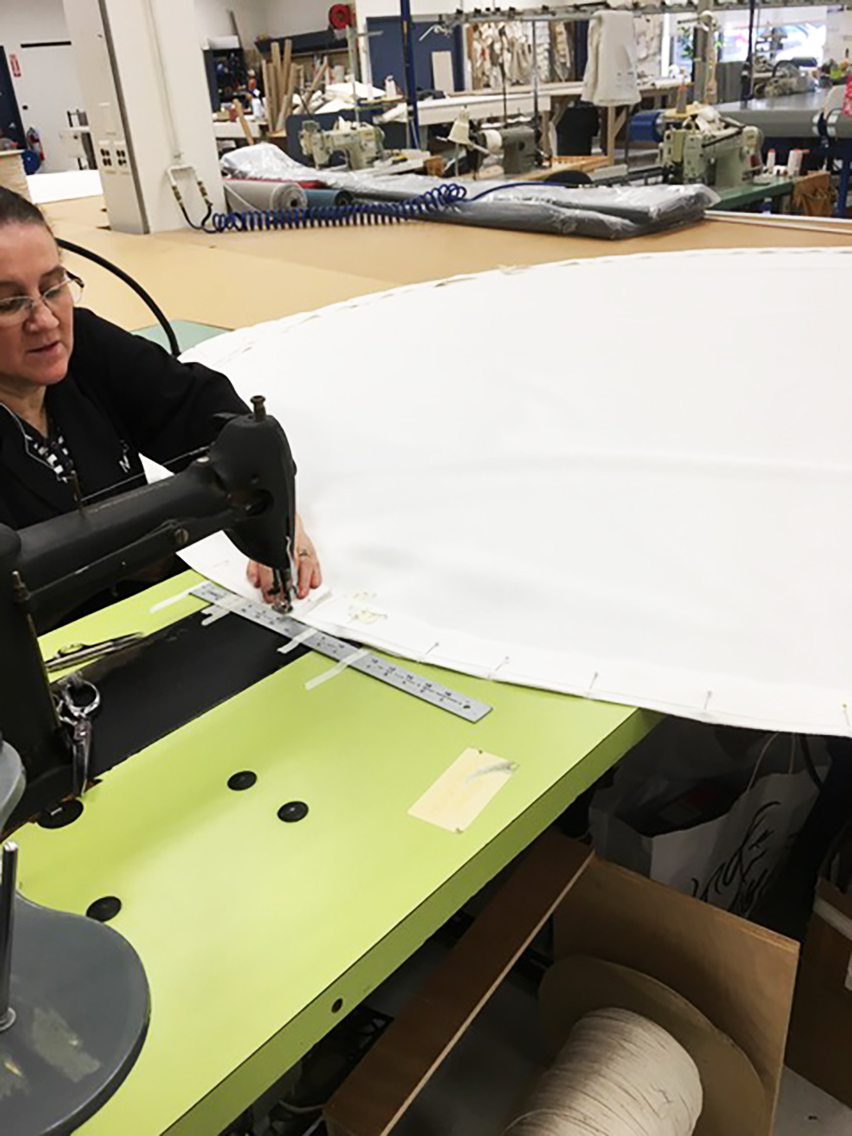
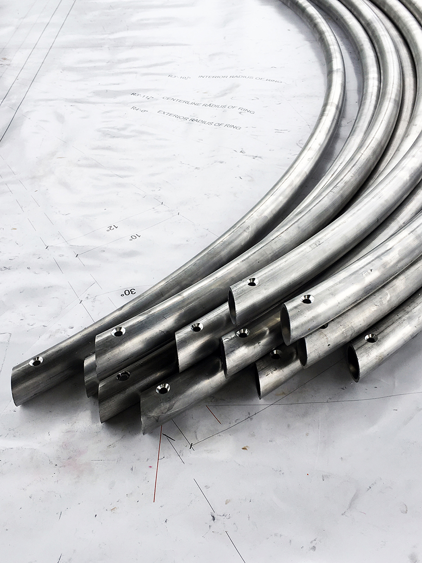
Canopy membrane detail mock; Stitching the membrane ant MS&G Workshop; The canopy rings | Credit: Eva Jensen Design
Canopy
Three segments of custom-bent aluminum tubing form the circular canopy. Each is connected by three-pronged 3D-printed joint nodes that we custom-designed in collaboration with Laufs Engineering Design. A static “Dyneema” rope line fastens the aluminum frame to the shading membrane by threading through the frame’s eye bolts, grommets located on the perimeter of the shading membrane, as well as through the embedded channels of the joint nodes themselves. Aluminum support poles are connected to the vertical prongs of the joint nodes. The canopy tilts six degrees and is fixed in place by T-handle pins.
The fabrication of the canopy membrane proved to be one of the more challenging parts of the design. We sought a material that offered breathability, a translucent quality, and a texture that would allow for the logo to be printed. After extensive research and testing, we came upon a new-to-market outdoor solar shade produced using nanotechnology and woven in a twill pattern. At Manhattan Shade and Glass’ Long Island City studio, we collaborated with technicians to determine the final membrane edge detail. The canopy membranes were machine-cut, but had to be completed manually using sewing machines.
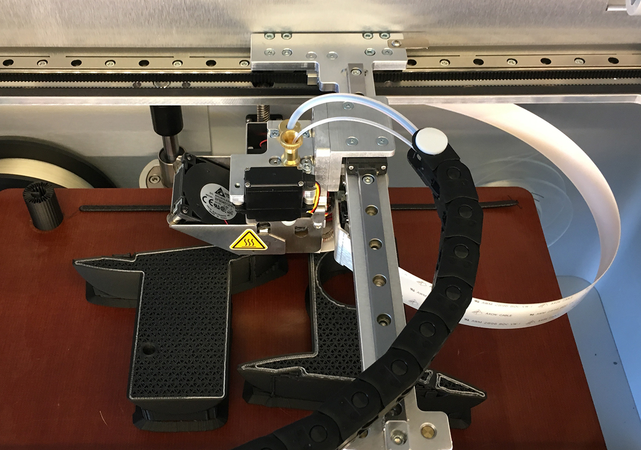
Joint Nodes & Brackets
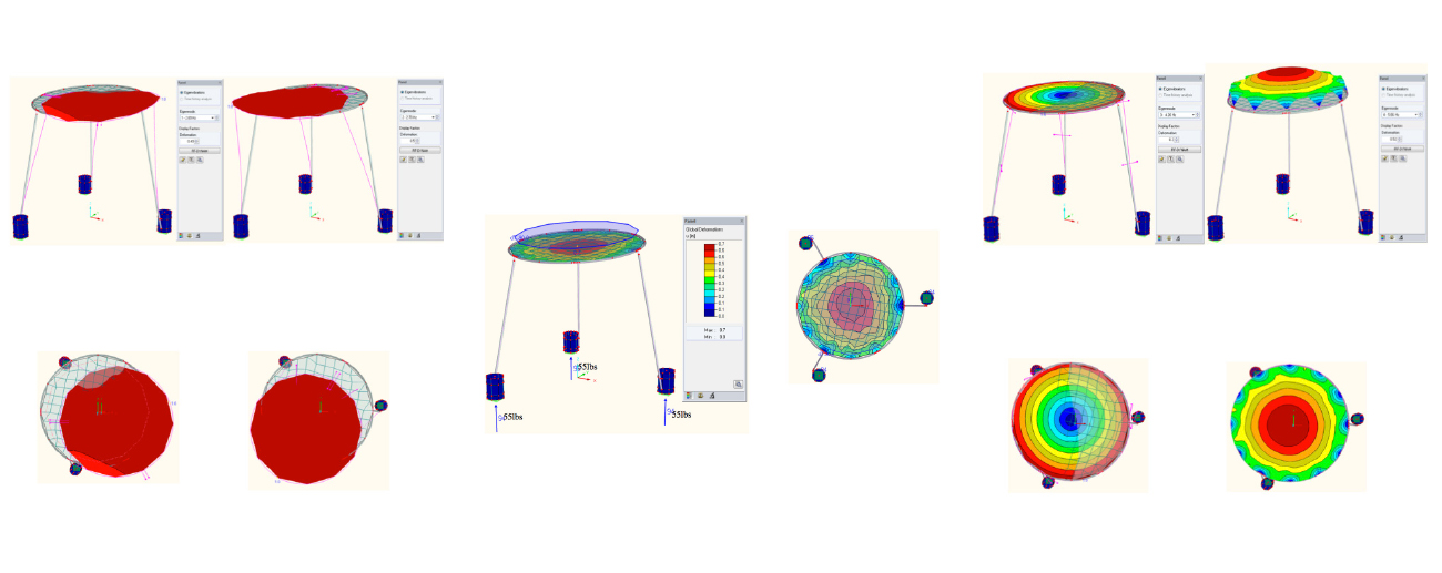
The concept for Circle Shade was conceived and developed in CAD software. For structural analysis of the four outdoor mobile canopy systems, we consulted structural engineer Laufs Engineering Design (LED), whose office is located in Long Island City near Socrates Sculpture Park.
The initial collaboration explored the joint nodes’ structural properties so that they could efficiently support a segmented eight-foot diameter ring and further enable it to sit on a tripod stabilized by counterweights. LED had experience using 3D-printing to fabricate canopy structures and their research demonstrated a range of customization methods that allowed for a more liberating formal exploration that pushed the limits of the joint nodes’ functional capabilities. Initially, the ring’s joint nodes were developed with a printed protruding eye-hook for lacing of the canopy to the ring. However, the 3D-printer was not able to place reinforcement fiber in this element, and, therefore, it was susceptible to breaking.
During the design development, we turned this particular 3D-print fabrication challenge into a guiding design parameter. We saw an opportunity to customize the joint nodes even further using 3D-printing technology to incorporate internal channels that served as conduits for the static “Dyneema” line that tethered the shading membrane to the aluminum ring. Thus, the joint nodes became an integrated design element serving to link the elements of the canopy with one another, the tripod poles, and the shading membrane.
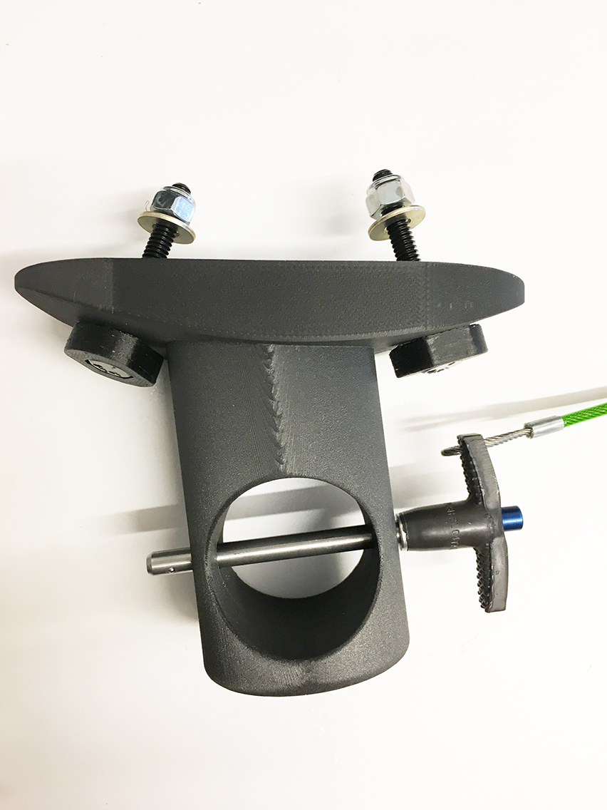
The 3D-printed counterweight brackets underwent parallel design development. Initially, they were designed as externally applied half-circular brackets with flanges for mounting. Through the design process, they became a pair of clean and simple offset cylinders protruding through holes in the curved face of the concrete counterweight with hidden interior curved plates for mounting. 3D printing allowed for an iterative design process that honed the customization of specific parts.
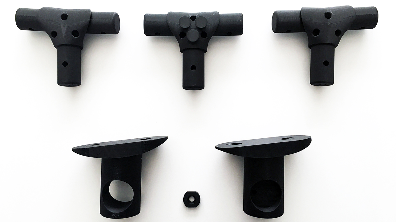
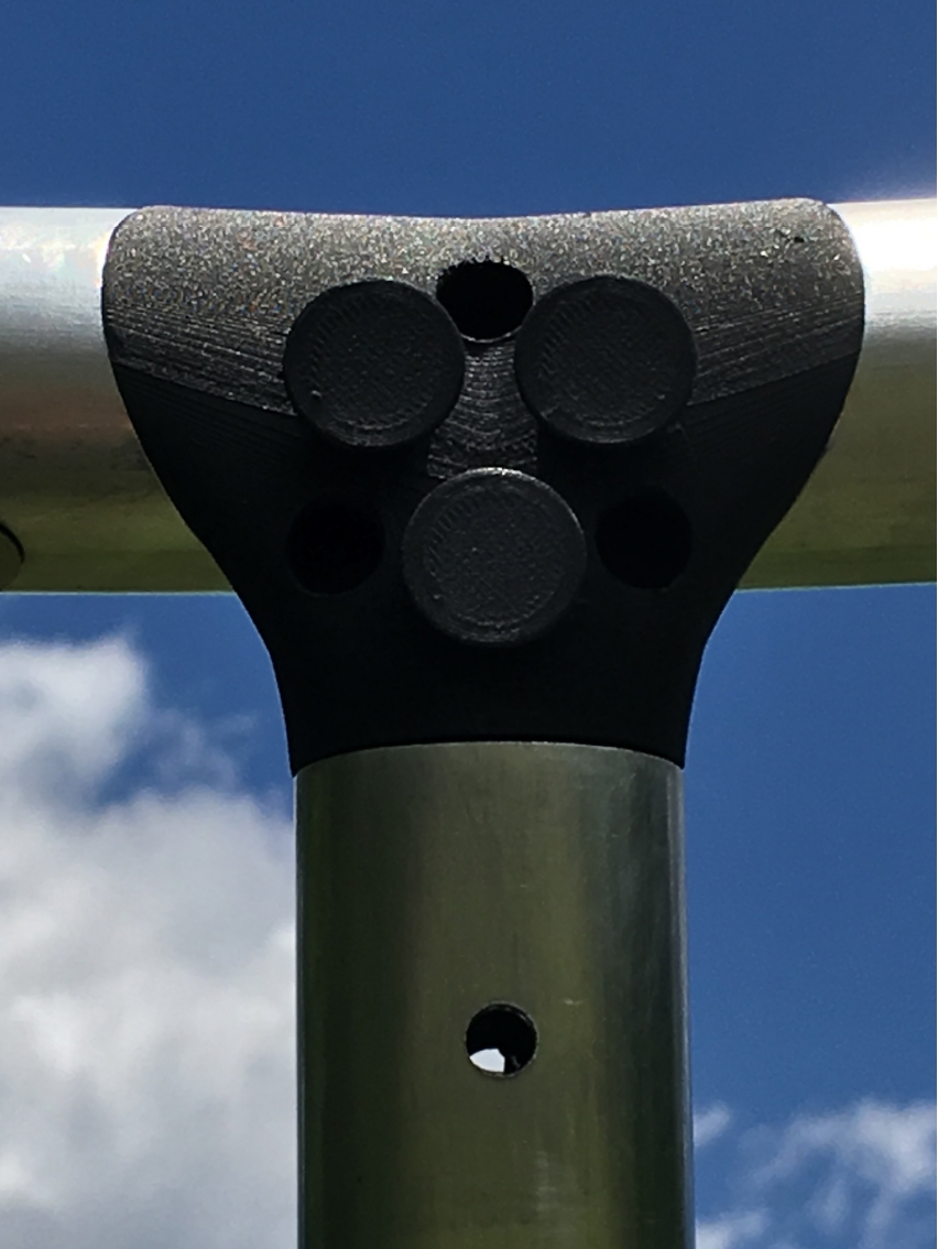
3D-Printed joint nodes (left, right) and counterweight bracket (middle) designed in collaboration with Laufs Engineering | Credit: Eva Jensen Design
The three-cleat node was a further iteration, and a gesture to provide for a start and finish of the fastening lace, allowing for future adjustments.The focused design iterations took advantage of 3D-print customization, as each node is slightly different. Prototyping during design development was only possible for certain parts: the 3D-printed joint nodes and brackets, the membrane, and the concrete counterweights. The four Circle Shade units produced are fabricated as prototypes created through 3D computation and model studies.
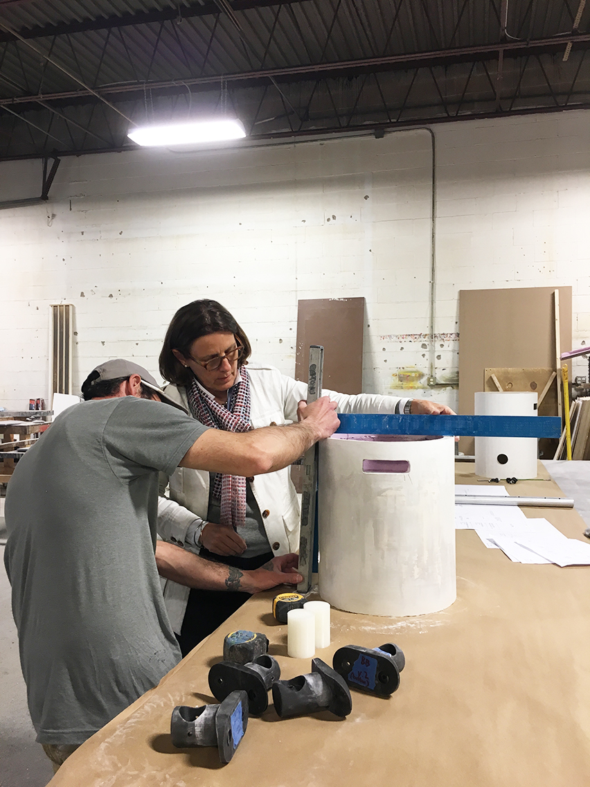
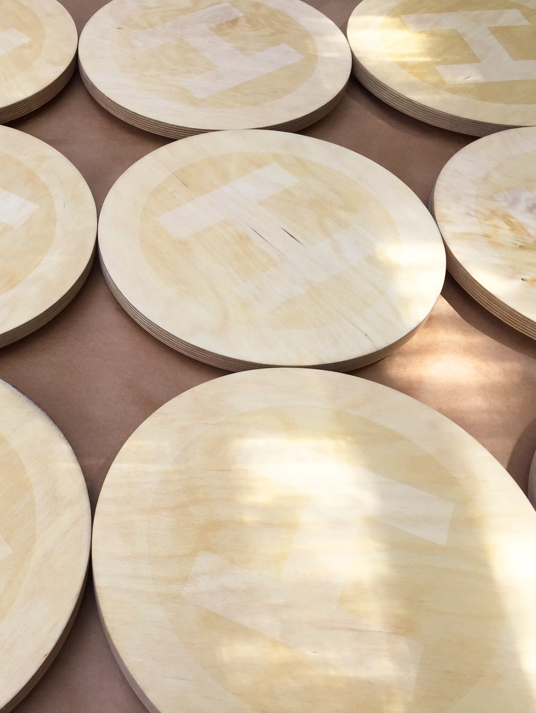
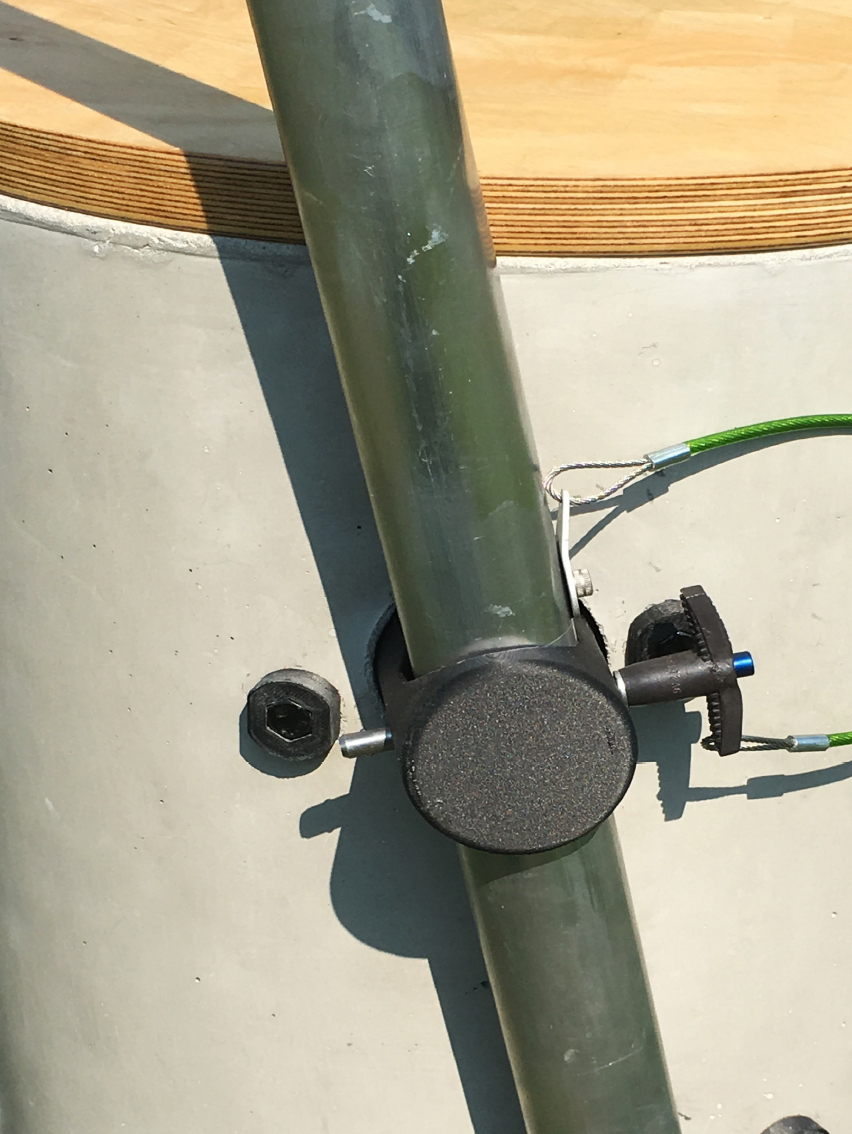
Reviewing the mold test at Truth Concrete; Seats branded with Socrates’ I-Beam logo; A counterweight, support, and 3D-printed bracket. Credit: Eva Jensen Design
Counterweights
Each Circle Shade structure is anchored by three cylindrical counterweights. The drums also function as stepstools for access to the canopy ring during assembly, as well as seats for visitors to the Park. The New York-based company Truth Concrete mold cast the concrete forms with fiberglass and other aggregate for reinforcement and weight control. Each counterweight includes two openings for handling and a removable plywood top. U-shaped hooks may be used to stake the counterweights’ interior bases to the ground for further support. On the sides of the counterweights, two offset cylindrical brackets protrude to hold aluminum poles in place at a 12-degree angle. The upper cylindrical bracket allows for the pole to pass through, while the lower brackets provide for an elevated base with drainage. The brackets are fastened with bolts mounted into 3D-printed grommets integrated with the interiors of the counterweights. The brackets, like the joint nodes, are 3D-printed and fabricated out of a nylon-carbon fiber composite with fused filament technology.
Explore
Circle Shade – 2πR4: Inspiration & poetics
Folly/Function 2017 winner Eva Jensen describes her design process.
Folly 2013: Talking treewood
A conversation with the 2012 and 2013 winners of the Folly competition.
In conversation: Jason Timberlake Austin, Aleksandr Mergold, and Elissa Goldstone
The winners of Folly 2014 discuss their practice.